.jpg)
Project Sponsor Initial Requirements: Design and Manufacture an eVTOL drone using a Tilt-Wing Configuration capable of transporting a 1 lb payload with a flight time of 19 minutes with a budget of $600. As the only Aerospace Engineering student on the team, my role was focused on the aerodynamic design and simulation of this drone while in horizontal cruise.
Having no prior experience with RC Planes, aircraft design, or fluid simulation software, my first challenge was to conduct research on previously designed Tilt-Wing Aircraft, methods and materials commonly used in RC Aircraft design and manufacture, and the softwares available to me that I could learn and apply.
Additional challenges included coordinating with mechanical engineering teammates, managing budget constraints, and ensuring the design met all performance requirements while remaining manufacturable within our timeline.
After weeks of reading engineering publications, discussing with Aerospace Department Professors and Graduate Students, I began my approach to the aerodynamic design challenge. What follows will be a description of my role and contribution to this project, written to best convey the series of events and decisions that were made as the project went along.
All aircraft are designed based on a set of initial requirements, and given that our drones's requirements were mission-focused as opposed to design-focused, my team and I had to first generate our own set of design parameters that we could base a conceptual design around. This set of design parameters was based upon 4 main tenets: Finanical Cost, Manufacturing Ability, Storage Ability, and Performance Efficiency.
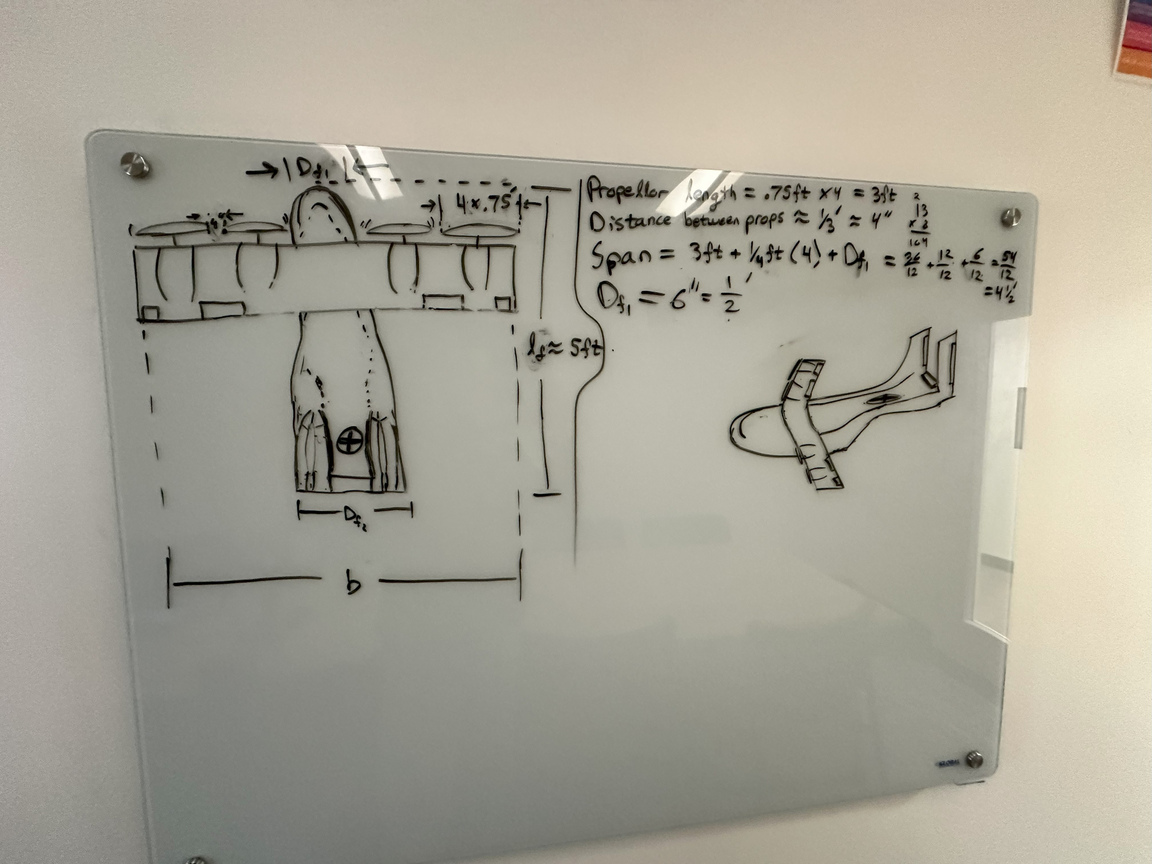
Inital Design Parameters: Wing Aspect Ratio = 6; Wingspan = 4 ft; Non-Swept Rectangular Wing with 4 Wing-Mounted Motors; Fuselage Length = 3 ft; Vertical Thrust-to-Weight Ratio = 1.5.
Once these design parameters were agreed upon, I began the conceptual design phase. After a multitude of conceptual sketches--consisting of varying wing/tail/fuselage configurations--were drawn up, a final design configuration was agreed upon by the team. The decided configuration was that of a conventional fixed-wing aircraft. This configuration was selected due to its relative ease of manufacture and my own familiarity with the mathematical performance modeling of conventional fixed-wing aircraft.
After a conceptual design was completed, I authored a MATLAB flight performance model using an Elliptical Lift Distribution assumption to guide preliminary decisions in Wing/Tail/Propeller sizing, maximum Gross Takeoff Weight, and design cruise speed. At this point in the project, the rest of my team had either purchased or aquired some of the electronics that would be used in our prototype. Specifically, they had acquired a set of motors and propellors for free. Integrating the motor rating, expected battery voltage, and propellor performance specs gathered online, I was able to calculate a series of estimated horizonal cruise speeds for our drone based on motor RPM. Furthermore, this allowed me more freedom to 'play around' with different design parameters that would provide me further insight into our drone's performance with different parameters. Most notibly, an Gross Takeoff Weight of roughly 8.5 lbs was determined.
When this Performance Model was presented to our project sponsor, she noted that while this model was not exactly incorrect, the simplifying assumptions (Elliptical Lift Distribution) used to write the code would only give me 'ballpark' performance estimations about our drone. It was at this point that she suggested I explore other aircraft design software that was available for free on the internet. This led me to the discovery of softwares like AVL, XFLR5, and OpenVSP with VSPAero.
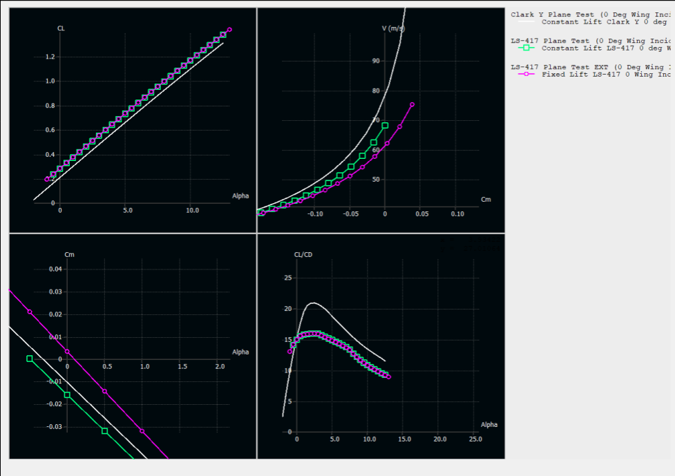
Through the exploration and use of these softwares I decided that using XFLR5 and OpenVSP would be in my best interest given their extensive CAD and CFD capabilities. I would like to note that XLFR5 was used extensively before OpenVSP, as it allowed me to quickly compare and contrast different Wing, Tail, and CG arrangements that would provide the optimal CM-alpha curves. Once an optimal arrangement was configured, I was also able to compare and contrast different airfoil shapes. Through a quick trade-study, it was determined that the LS-417 Airfoil would be used due to its horizontal cruise speed of around 45 mph--a speed that my team and I agreed would be in our best interest due to power constraints and ease of pilot control.
At this point in the project we had reached about the halfway point to our deadline. By networking with UCI project teams and meeting with UCI Aerospace Professors, my teammates had acquired a collection of free components to use for our project. Most importantly, they had acquired an entire RC plane that had been used for a similar project years prior. This aircraft came with a fuselage, wing, horizontal and vertical tails, and useful electronics. This pre-built kit aircraft became the base of our second prototype.
It's here I would like to note that an initial half-scale prototype had already been constructed and tested by the rest of my team, however my involvement was limited due to the prototype's focus on vertical hover, tilt-wing actuation, and electronics integration.
The fuselage of our new prototype was measured to be roughly 4 1/2 ft from nose to tail, which was longer than our inteded design. To correct this, I cut the rounded nose off of the fuselage and removed a 1 ft section from the back of the fuselage while keeping the tails intact. The goal of this was to inevitibly replace the nose with a rounded piece of pink foam to mitigate damage to our prototype during the inevitible nose-dive crash, and to reattach the tails to the fuselage using a series of carbon fiber rods, 3D printed shaft collars, and 3 wooden frame inserts to guide these rods. This design would allow my team and I to adjust the tail arm of our prototype by about 3 inches during testing should the aircraft demonstrate undesirable stability.
The design and manufacture of this adjustable tail arm feature was done by myself and with the help of my project lead. The details of this feature can be found below in the accompanying pictures and their captions.
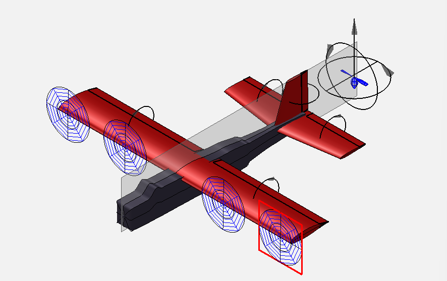
Once the fuselage modifications were complete, I returned to my aerodynamic analysis with the use of OpenVSP and VSPAero. Using OpenVSP's CAD features, I measured and modeled our aircraft. Through my previous research, I discoved some studies discussing the effects of blown lift due to wing-mounted propellors, as well as how using wingtip-mounted propellors could reduce the effect of wingtip vorticies on an aircraft's induced drag coefficient. This drove me to begin using OpenVSP's built in Aerodynamic Modeling feature 'VSPAero'. I conducted a trade study that compared wingtip-mounted propellors with midwing-mounted propellors and found that for our current prototype, wingtip-mounted propellors would reduce our horizontal cruise induced drag coefficient by 6%. This study was passed along to my team member that was tasked with manufacturing our wing, and was then integrated into our wing design.
I would like to note that our wing design had already incuded the use of 4 motors evenly spaced throughout both wings, but did NOT have the outermost motors mounted at the very tip of each wing. The VSPAero analysis that was conducted ONLY included 2 motors on the aircraft in order to compare directly the difference between a midwing-mounted motors and a wingtip-mounted motor.
I would also like to speak breifly about my role in the design and manufacture of the wing itself. The task of design and manufacture of the wing was one that was NOT assigned to me in this project, however I was consulted numerous times during the completion of this task given my role as Aerodynamic and Design Engineer. A final prototype wingspan of 4.5 ft, Aspect Ratio of 6 was and an aileron coord length of 1 inch was decided upon, with all other previous parameters held the same.
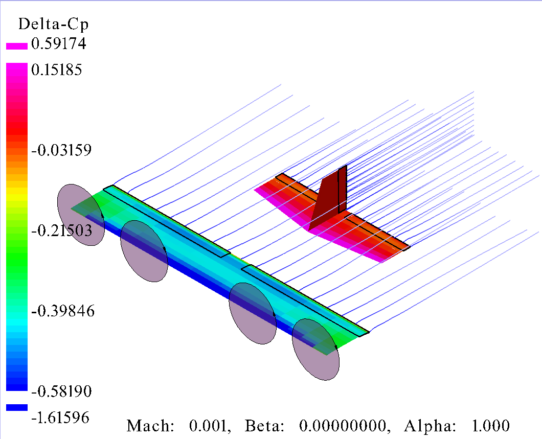
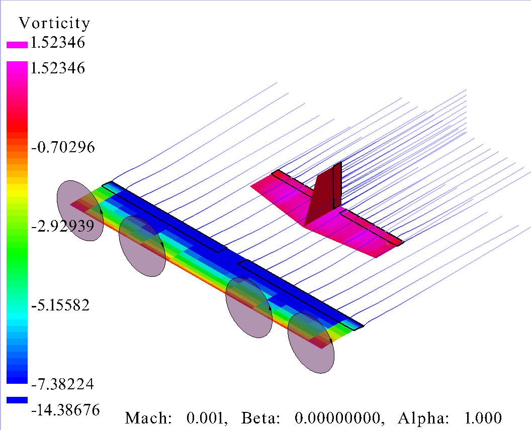
At this point, the completed prototype design had been modeled in OpenVSP and VSPAero had been used to analyze the expected horizontal cruise behavior of our prototype. The scope of information that VSPAero provides, as well as the advanced analysis possible through the use of specific settings adjustment fall far beyond what I was able to comprehend and learn during the time of this project, so the provided data that was most useful to me became the drag polar, CM-alpha curve, delta-cp vs alpha simulation, and the vorticity vs alpha simulation. These charts and figures are provided below, and represent the farmost acheivements I accomplished during my time on this project.
As these simulations were completed, the construction of our prototype was also. It is important to note that as the project continued, the payload requirements were dropped altogether and the required flight time was reduced to 15 minutes due to conflictions between battery capacity and battery weight.
As the project neared its final weeks, my team and I began our first tests. We decided that it would be most important to test our prototype's hover capabilites first, as the VTOL feature was our foremost requirement. Some videos of these tests are available below, however at this time I am unable to upload large file sizes to this page, and therefore cannot display all the tests that were conducted.
In the end, the team and I were not able to accomplish our goal of designing and manufacturing a functional Tilt-Wing eVTOL Drone within the amount of time available. Challenges that arose during our Hover Tests proved to cost us more time than we had available before graduation.
While our project may have not ended with the results that we wanted, I feel incredibly greatful for my team and all of those that helped us along the way. What I have learned about Aircraft Design and the experience that I have gained from this project are incredibly invaluable to me, and have inspired to pursue a career in Aerospace Design.
If you have any questions about this project or would like to discuss it with me further, please feel free to contact me.
- Designed and manufactured a prototype Tilt-Wing eVTOL drone
- Discovered and self-taught useful Aircraft Design specific softwares like OpenVSP and XFLR5.
- Reduced anticipated cruise induced drag by 6% through optimization studies in VSPAero
- Successfully designed and manufactured an adjustable tail arm system for horizontal stability testing
- Developed comprehensive MATLAB performance model for design guidance
- Completed project within $600 budget constraint
.JPEG)
.jpg)
.jpg)
.jpg)
.jpg)
.jpg)
.jpg)
.jpg)
.jpg)
.JPG)
.JPG)
.jpg)
.jpg)
.jpg)
eVTOL Hover Test Stand
Hover Test Stand footage of the Tilt-Wing eVTOL prototype 2
eVTOL Flight Test
Hover Test flight footage of the tilt-wing eVTOL prototype
eVTOL Flight Test
Hover Test flight footage of the tilt-wing eVTOL prototype
eVTOL Flight Test
Hover Test flight footage of the tilt-wing eVTOL prototype
Client
Mechanical Senior Capstone Design Project
Duration
6 months
Team Size
6 engineers
Year
2025